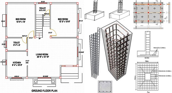
Some important thumb rules for making the layout of any Column
Guidelines to be followed for making A column layout is created on the basis of the following directions :-
The design of columns should be made with regard to the total forces operating on the structure. In order to avoid errors, there are some important thumb rules which should be followed by every Civil engineer and Architect.
The following three thumb rules should be followed:
1. Size of the Columns
2. Spaces among Columns
3. Alignment of columns
Minimum Size of RCC columns: The size of the columns is based on the total loads operating on the columns which range from axial loads and lateral loads. Large beam spans cause bending moment in the beams as well as in columns which are drawn by the stresses in the beams.
To apply this general thumb rule, presume a structure of G+1 floors high, with standard 6? walls. Least size of an RCC column should not be under 9? x 12? (225mm x 300mm) with 4 bars of 12 MM Fe415 Steel.
The dimension of the column should be 9? x 12? (225 mm x 300mm) with 6 bars of 12 MM Fe500 steel. It is recommended to utilize M20 grade concrete for the structure (ratio 1 part Cement : 1.5 parts Sand : 3 parts Aggregate with 0.5 parts water by volume). It is also suggested to utilize 8 MM stirrups at a span of 150 MM center to center all through the length of column.
This setup of 9? x 12? RCC columns is secured for G+1 Floors.
Spaces (distance) among two columns: To install the above column, a distance of up to 5 meters should be maintained. It is suggested to apply beams of size 9? X 12? (225 MM x 300MM) having a slab thickness of 5? (125 MM) cast in M20 concrete for spans up to 5m. Some other factors like secondary and tertiary spans, point loads and wall loads which should also be taken into consideration. The thumb rules can be useful when the structure is simple.
Recommended use of steel for a beam 5 meters long, secondary spans of up to 4 meters, wall loads of up to 8 kN per running meter :-
? Top Steel ? 2 bars of 12 MM
? Crank bars ? 2 bars of 12 MM, cranked at an angle of 45? at a span of L/4 at both ends of a simply supported beam
? Bottom Steel ? 3 bars of 12 MM.
This configuration can be customized based on several factors.
Alignment of Columns: The columns should be arranged on the basis of the plan. A grid column placement is highly solicited to minimize the point loads and avoidable complications at the time of construction. It significantly minimizes the construction cost and time necessary for construction.
Beams connected with other simply supported beams contain reduced bending moments, and thus need less steel and concrete depth to maintain safety.
Columns should be attached with each other for transmitting the loads safely. An expert planner should consider these things while planning the structure.


