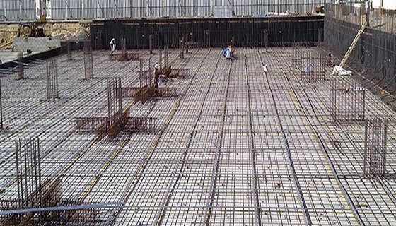
How to create the design of the Raft Foundation

If the columns transfer heavy loads to a structure or the acceptable soil pressure is too small that specific footings have to cover in excess of one-half of the area, a continuous footing should be arranged under all columns and walls.
This type of footing is known as a raft or mat foundation. Raft foundations are useful for minimizing the settlement of structures situated over extremely compressible deposits. As rafts are placed generally at some deepness in the ground, a huge volume of excavation is essential.
If weight of the excavated soil is similar to the weight of the structure and that of the raft, and the center of gravity of excavation and structure match, settlement will be insignificant. If complete compensation is not plausible, a shallower raft is allowed when the net increase in loads is too little to produce tolerable settlement. The shape of a raft foundation is rectangular or circular and may be with or without an open.
If the columns are placed maintaining equal gaps and loads are not too heavy, a raft will be designed containing unvarying thickness. The customary design of such a raft comprises determining its dimensions, from which the soil pressure is worked out at different locations below the slab. The raft is segregated into a slew of continuous strips placed at the center on the correct columns and rows in both directions. The shear and bending moment diagrams is sketched with continuous beam analysis or coefficients for each strip. The depth is chosen to meet shear requirements.
The steel requirements will fluctuate from strip to strip. This process provides a conventional design as the interaction of adjacent strip is ignored.
If the columns are placed at equal distances and their loads are identical, the pressure on the soil is constant; else moments of the loads are assumed about center of the base and pressure distribution is set. As the equations for this, are generally obtained for an inflexible member and a raft in general is not an inflexible member, the pressure and subsequent internal stresses may be inaccurate when the eccentricity is very big. The weight of the raft is not taken in the structural design as it is expected that the subsoil will bear weight directly.
Raft is ribbed when the column spacing is uneven or a considerably thin slab is used across most of the area 4. On the other hand, rafts are condensed at the column locations for economy and there should be adequate depth to withstand shear. A ribbed raft foundation contains a slab that functions with ascending soil pressure at its base and supported with beams from column at its upper which balance the ascending pressure with descending column loads. It is identical to a floor slab supported with a system of beams and columns. The portion among beams is plotted as a customary one way or two way slab. If the beams are deep, they should be arranged as deep beams.

Ref.: theconstructor.org
|