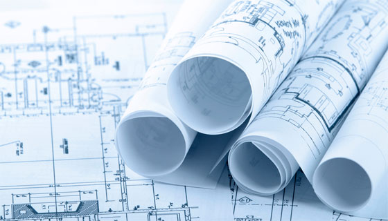
Set of construction drawings & specifications necessary for developing a building

In order to complete any construction project (building) successfully, proper arrangement of construction documents, drawings, sketches and plans is necessary. In a construction project there may be various types of documents which can fulfill the need of several clients and buildings.
he estimated budget of the construction project can be influenced significantly with the modification in the drawing requirements. Still, some specific conventions are mostly recognized. Given below the detailed lists of drawings generally found in a typical Set of Construction Documents:
1. Architectural Drawings: An architectural drawing refers to a technical drawing concerning a building (or building project). The architects utilize it to create a design idea & transform into a logical proposal for conveying ideas and concepts as well as assuring clients of the merits regarding a design. Besides, a building contractor gets benefitted to develop the building with architectural drawings as well as use these as a record of the accomplished work, and the record of a existing building.
The lists provided below are the standard components available in a complete set of Architectural Construction Drawings:
Setting Out Plan, Floor Plans, Elevation Drawings, Section Drawings, Workign Drawings, Opening Schedules, Rood Drainage Plan, Flooring Plan, Furniture Plan, Typical Details
2. Electrification Drawings: The following drawings represent the location of electrical equipment and their blueprint in the building.
Electrical Legend, Floor Lighting Plan, Floor Power Plan, Single Line Diagram, Fire Alarm Layout, Floor Sound System and CCTV Camera, Equivalency Chart, Lightening Protection Earthing Details.
3. Public Health Drawings: These types of drawings are categorized as follow :-
Legend and General Notes, Sewerage and Rainwater Layout Plan, Manhole Schedule, Plumbing Construction Details, Water Supply Layout.
4. Structural Drawings: These drawings represent the support system of the building that ranges from how the building is positioned, types of structural components of the building, the required strength of the building as well as how beams, columns, stairs, slabs etc. are interlinked. The structural drawings contain the following elements :-
General Notes, Typical sections, Foundation excavation plan, Footing sections, Ground floor column plan, Column sections, Ground floor plinth beams plan, Plinth beams sections, Ground floor beam plan, Beam sections, Ground floor slab bottom rebar detail, Ground floor slab top rebar detail, Ground floor slab section, Overhead water tank design, Septic tank design.
5. Fire Fighting Drawings: The following items are included in the fire fighting drawings :-
Legend and Notes, Fire Fighting Layout Plan (For Each Floor).
6. HVAC Drawings: The HVAC drawings consist of the following :-
Legend and General Notes, AC Layout Plan (for each Floor), Equipment Schedule and Installation Detail.

Image Courtesy: balmoralconstruction.com
|