Engineering Drawing and Sketching

This is an exclusive article on how to apply various engineering drawing & sketching written by Ernesto E. Blanco, David Gordon Wilson, Sherondalyn Johnson, and LaTaunynia Flemings.
The engineers can convey their ideas in a better way with some sort of pictures or drawing. Generally there is difference between sketching and drawing. Sketching usually refers to freehand drawing whereas drawing is performed by applying various drawing instruments like compasses to computers to make the drawings dimensionally perfect.
Engineering Drawing Index
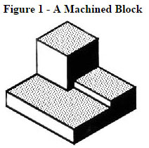
Image Courtesy: me.umn.edu
|
Isometric Drawing: The picture of the object demonstrated in figure 2 is known as isometric drawing. It represents one of a family of 3d views termed as pictorial drawings. The vertical lines of an object are drawn in perpendicular and the horizontal lines placed in the depth and planes are drawn at 30 degrees to the horizontal in an isometric drawing. If drawings are created by following these instructions, the lines parallel to these three axes maintain their perfect (scale) lengths. Unparallel Lines to these axes does not maintain their exact length.
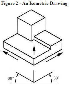
Image Courtesy: me.umn.edu
|
Any engineering drawing depicts various things. A objected is clearly defined with the drawing. It is best to present the all details as well as dimensions on a single drawing through the isometric drawing.
One can put in several crucial informations into an isometric drawing. In case of an object, as shown in figure 2, contains a hole on the reverse side, it may be invisible through a single isometric drawing. To have a more detailed view of the object, an orthographic projection is necessary
Orthographic or Multiview Drawing: In figure 3, you will find an object that is suspended with see-through threads within a glass box.
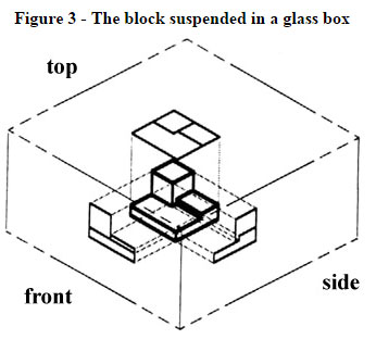
Image Courtesy: me.umn.edu
After that, create the drawing of that object on each of three faces as visible from that direction. Unfurl the box as shown in figure 4 and there will be 3 types of views. It is termed as an "orthographic" or "multiview" drawing.
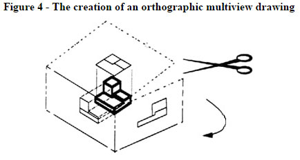
Image Courtesy: me.umn.edu
In Figure 5, you will get the three views presented on a piece of paper after unfurling the box.
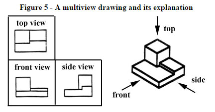
Image Courtesy: me.umn.edu
In order to select the views for a multiview drawing, you have to opt for the views which represent each detail concerning the object. It is not obligatory to get the three types of views. You may require several views useful for defining the object completely. As for instance, some objects only require two views, whereas others require four. For the circular object, as shown in figure 6, there are only two views.
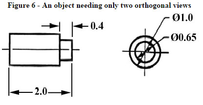
Image Courtesy: me.umn.edu
Dimensioning
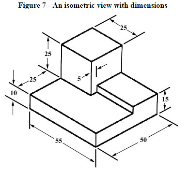
Image Courtesy: me.umn.edu
|
In figure 7, the object is dimensioned in the isometric drawing. Generally, for dimensioning purpose, an object should be created and dimensioned in the most suitable manner. Provide various dimensions precisely as required by the craftsperson to craft it -no more, no less. Restrain from providing unnecessary dimensions. These will lead to mess the drawing and if "tolerances" or accuracy levels are given, the unnecessary dimensions frequently produce conflicts when the tolerance allowances can be added in different ways.
If measurement is made from one point to another simultaneously, error may occur inevitably. So, it will be better to start the measurement from one end to several points. Thus the dimensions will be provided with a reference standard. It is suggested to maintain the order for selecting the placement of the dimension. It should be followed by a machinist for generating the part.
Sectioning: It happens several times that the interior details of an object is invisible from the outside (as shown in figure 8).
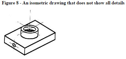
Image Courtesy: me.umn.edu
This problem can be solved by assuming to slice the object on a plane and demonstrating the "sectional view". The sectional view is relevant to objects like engine blocks, where the interior details are complicated and it becomes problematic to recognize with the help of "hidden" lines. Generally hidden lines refer to dotted line located at an orthographic or isometric drawing.
Read More: Engineering Drawing and Sketching (Page 2)
|