Engineering Drawing and Sketching

Lets imagine that the object is cut through the middle as shown in figure 9.
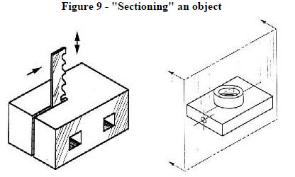
Image Courtesy: me.umn.edu
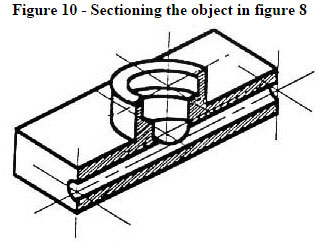
Image Courtesy: me.umn.edu
Image Courtesy: me.umn.edu
|
Subtract the front half as shown in figure 10 and you will obtain a complete section view as shown in figure 11.
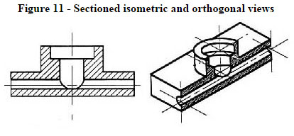
Image Courtesy: me.umn.edu
The cross-section will be shown in figure 11 if it is observed from straight ahead.
Drawing Tools: For creating a drawing, the manual drafting instruments (as shown in figure 12) or computer-aided drafting or design, or CAD can be applied. The basic drawing standards and conventions are identical devoid of type of design tool that is used to prepare the drawings. In learning stage of drafting, the manual drafting process shoule be applied. If the drawing is created devoid of applying either instruments or CAD, it is known as a freehand sketch.
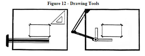
Image Courtesy: me.umn.edu
|
"Assembly" Drawings: In figure 13, there is demonstration for an isometric view of an "assembled" pillow-block bearing system. It represents the actual view of the object from a specific angle. But here it is not possible to get the view of inside part.
The isometric views of the pillow-block are obtained if these are divided into parts or disassembled as shown in figure 14. It will help to get the view of the inner components relating to bearing system. Isometric drawings can evidently demonstrate the overall arrangement, but not provide the details and the dimensions.
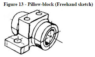
Image Courtesy: me.umn.edu
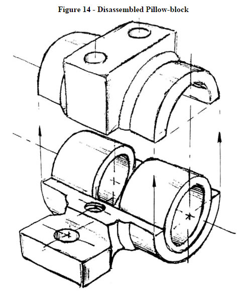
Image Courtesy: me.umn.edu
Cross-Sectional Views: The representation of a cut-away portion of the object as well as hidden components in a device can be obtained through a cross-sectional view.
Suppose a plane is sliced vertically by the center of the pillow block as shown in figure 15. Then visualize detaching the material from the front of this plane, as presented in figure 16.
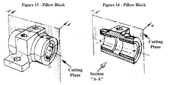
Image Courtesy: me.umn.edu
The figures given above show the demonstration of the unused rear section. Diagonal lines (cross-hatches) provide regions where materials are sliced through the cutting plane.
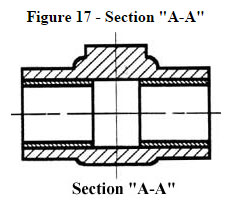
Image Courtesy: me.umn.edu
This cross-sectional view as presented in section A-A, figure 17, is orthogonal to the viewing direction, illustrates the co-relation between lengths and diameters in superior manner. These drawings can be generated easily as compared to isometric drawings. Seasoned engineers can define orthogonal drawings devoid of requiring an isometric drawing.
Read More: Engineering Drawing and Sketching (Page 3)
|