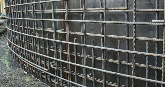
Minimal Steel Reinforcement in Concrete and necessity for Clear Cover

The least amount of steel reinforcement is characterized as that for which "peak load at first concrete cracking" and "ultimate load after steel yielding" are identical. By following this method, any brittle behavior and any localized omission are bypassed when the member is free from over-reinforced.
In simple terms, there exists a reinforcement percentage range on the basis of the size-scale, through which the plastic limit analysis is exercised containing its static and kinematic theorems.
A least area of reinforcement is necessary to check the cracking that may take place in the concrete because of temperature, shrinkage and creep. It allows cracking being allocated equivalently and hence reduces individual crack width.
The following standards are used to establish the cross-section area of temperature or lowest reinforcement essential for hydraulic structures. The percentages are obtained from the gross cross-sectional area of the concrete to be reinforced. Here the width of the section surpasses fifteen (15) inches (380 mm), a width of fifteen (15) inches (380 mm) is applied in ascertaining the temperature or least reinforcement requirement.
The lowest ratio of necessary reinforcement is;
FOR SLABS:
fmin = 0.002 (for fy = 40,000 psi)
Smin = 0.0018 (for fy = 60,000 psi)
FOR WALLS:
For Vertical Steel
fmin = 0.0015
For Horizontal Steel
fmin = 0.0025
The temperature reinforcement should remain between ½ inch at nine 9 inch center to center. All concrete stilling basins, glacis and floors and all concrete aprons structures (containing slab thickness > 15 inch ) shall be reinforced in the exposed (top) face having ¾ inch bars at twelve (12) inch center to center, both ways, positioned three (3) inch clear from concrete face, if nothing else is designed.
Nominal reinforcement of concrete chute blocks, baffle blocks and sills for stilling basins, aprons and other portion of structures shall include ¾ inch bars at twelve (12) inch center to center, both.
Temperature and shrinkage reinforcement must be allocated equivalently alongside faces of structure elements to avoid cracking because of variation in temperature, creep, and shrinkage.
Based on the thickness of the structural element, it is suggested that the centre-to-centre spacing of the primary and secondary reinforcement should be identical to or less than 300 mm; conversely, it must not surpass 450 mm. The lowest clear distance amid bars should remain between 1.4 times the bar diameter or 1.4 times the minimal maximum size of the coarse aggregate, whichever is higher. It is also applicable to the clear distance amid a contact lap splice and adjoining splices and bars.
For more information, visit www.aboutcivil.org

Image Courtesy: apolloconcretetanks.com.au
|