Engineering Drawing and Sketching

The top "outside" view of the bearing is an orthogonal (perpendicular) projection. A projection is a liner transformation from one to another. An orthogonal projection systemizes and generalizes the concept of graphical projection. Notice the direction of the arrows for the "A-A" cutting plane.
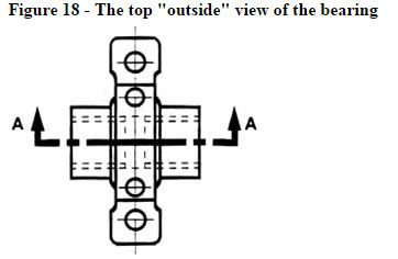
Image Courtesy: me.umn.edu
Half sections: In a Half section object, it is showing one half of the view in section. A centerline divides halves into parts. One should draw the visible lines that define the top full sectional view of the object.
Full and sectioned isometric views: A full section view is made by passing the imaginary cutting position completely through the object. All the hidden characteristics crossed by the cutting plane are represented by visible lines in the section view. The oblique lines on the section drawing are accustomed to indicate the territory that has been on paper cut. These lines square measure referred to as section lining or cross-hatching. The lines are skinny and are sometimes drawn at a 45-degree angle to the key define of the thing.
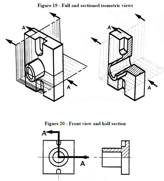
Image Courtesy: me.umn.edu
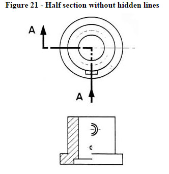
Image Courtesy: me.umn.edu
|
Front view and half section: A second, infrequent use of cross-hatching is to point the fabric of the article. One style of cross-hatching is also used for forged iron, another for bronze, so forth. In most cases, the kind of fabric is indicated elsewhere on the drawing, creating the employment of various styles of cross-hatching surplus.
Half section without hidden lines: Only for the dimensioning purpose, hidden dotted lines are used on the cross-section. Half sections are created by passing an imaginary cutting position only halfway through an object. Hidden lines are omitted on both halves of the section view. Half selection views are used most often on parts that are consistent, such as cylinders.
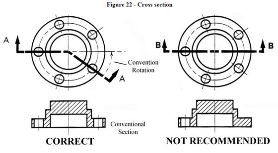
Image Courtesy: me.umn.edu
|
Sectioning Objects with Holes, Ribs, Etc.: The cross-section is the intersection of a body in three-dimensional spaces with a plane. The cross-section is an effective area that quantifies the essential possibility of a dispersion event. . However, the convention in a drawing is to show the view on the left as the preferred method for sectioning this type of object.
Dimensioning: Dimensioning is the three-dimensional process of estimating the area that an object occupies. With proper dimensioning, one can get a distinct and comprehensive definition of an object. A complete set of dimensions are necessary when ne interpretation required to build the part. Dimensioning is based on the following principles.
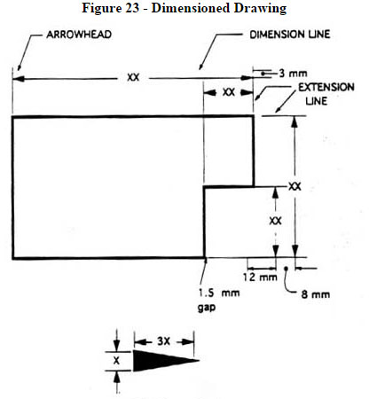
Image Courtesy: me.umn.edu
- Accuracy: There should perfect values.
- Clearness: dimensions should be assigned in proper positions.
- Completeness: everything must be included without any duplication.
- Readability: the proper line quality should be present for legibility.
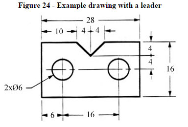
Image Courtesy: me.umn.edu
|
The Basics: Definitions and Dimensions: Dimensions are used to describe the size and location of features on part of manufacture. Dimension lines outline the parameters of a dimension. Dimension lines area unit lean lines ending in arrowheads and, broken the center to permit the position of the dimension price. The point is some three millimeter long and one millimeter wide. That is, the length is roughly thrice the breadth. Associate in nursing extension line extends a line on the item to the dimension line. The primary dimension line ought to be some twelve millimeter (0.6 in) from the item. Extension lines begin one.5 millimeter from the item and extend three millimeter from the last dimension line.
Example drawing with a leader: A leader may also be used to indicate a note or comment about a specific area. When there is limited space, a heavy black dot may be substituted for the arrows, as in figure 23. Leaders or leader lines are thin lines are used to connect a specific note to a feature. It also used to direct dimensions, symbols, item numbers and part numbers on a drawing. Also in this drawing, two holes are identical, allowing the "2x" notation to be used and the dimension to point to only one of the circles.
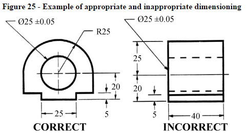
Image Courtesy: me.umn.edu
Where to Put Dimensions: The dimensions ought to be placed on the face that describes the feature most clearly. Samples of acceptable and inappropriately assigned dimensions area unit are shown in this figure.
To get the clean ideas on dimension, just select a simple rectangular block. The 3 dimensions will be most suitable to define the object perfectly. There are limited options to select the position of the dimensions to be placed.
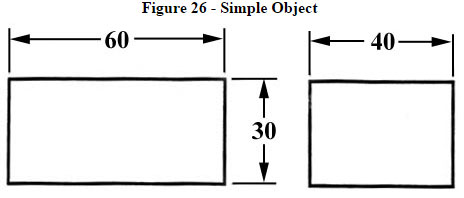
Image Courtesy: me.umn.edu
|
We have to create some selections once we dimension a block through a notch or cutout. Sometimes, it is recommended to make the dimension out of a standard line or surface. It is called as the data point line of surface. This reduces the inclusion of measure or machining inaccuracies which may occur from "chain" or "series" orienting. Notice however the size originates on the data point surfaces. In fig 27 & 28 only one datum is selected for each. If we can maintain the uniformity, everything will be identical. (Here, only the top view is demonstrated).
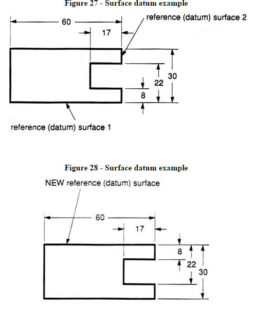
Image Courtesy: me.umn.edu
In figure 29, there exist hole and it is selected to make dimension on the left side of the object. The Ø denotes "diameter".
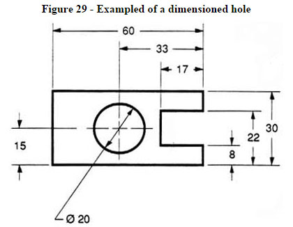
Image Courtesy: me.umn.edu
If the left side of the block is "radiuses" as shown in figure 30, the generally followed rule that the dimensions should not be replicated, is violated. We can measure the complete length as the radius of the curve located on the left side is accessible. In order to get a clear idea, the overall length of 60 is included here and it is a reference (REF) dimension. So it signifies that it is not needed in reality.
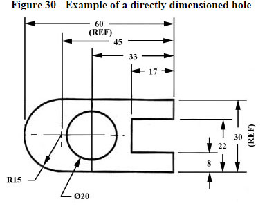
Image Courtesy: me.umn.edu
The proper information should be provided for unit of measurement used (e.g. inches and millimeters ) as well as the scale of the drawing in some portion of the paper, generally at the bottom.
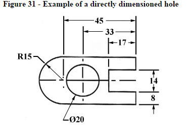
Image Courtesy: me.umn.edu
This drawing is proportional concerning the horizontal centerline. Centerlines (chain-dotted) are applied for uniform objects, as well as the center of circles and holes. In fig. 31, the dimension is made directly to the centerline. In some cases this process is more prominent as compared to make dimensioning amid surfaces.
|